
The "Member Editor" component allows you to modify the individual or several member plates in the Steel Joints add-on.
You can use the chamfer, notch, rounding, and hole operations with multiple shapes. It is possible to apply both operations, "Notch" and "Chamfer", for several member plates.
In this way, you can notch flanges from I-sections, for example (see the image).
Go to Explanatory Video
Curved elements are available only in RFEM. It's possible to intersect curved surfaces and solids.
When doing this, the program generates surfaces with the "Trimmed" surface type. With this technology, you can create very complex geometries, such as pipe intersections or curved openings, with a single click.
The intersection of solids is carried out adaptively using the new solid types "Hole" and "Intersection", according to the set theory. Use this method to create new, complex solid geometries similar to the manufacturing process (drilling, milling, turning, etc.). Therefore, it is possible to create complex curved surface or perforated solid elements. It's a simple process!
Go to Explanatory Video
You know for sure that when connecting tension-loaded components with bolted connections, you need to consider the cross-section reduction due to the bolt holes in the ultimate limit state design. The structural analysis programs also have a solution for this. In the Aluminum Design add-on, you can enter a member local section reduction for this. Enter the reduction of the cross-section as an absolute value or as a percentage of the total area at all relevant locations.
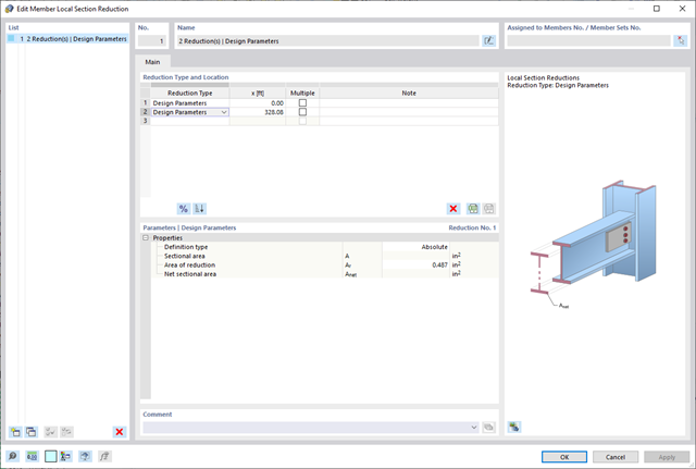
Please note that when connecting tension-loaded components with bolted connections, you need to consider the cross-section reduction due to the bolt holes in the ultimate limit state design. But don't worry, this can be easily done in the program. In the Steel Design add-on, you can enter a member local section reduction – and that's it. You can enter the reduction of the cross-section as an absolute value or as a percentage of the total area at all relevant locations.
The program can also help you here. It determines the bolt forces on the basis of the calculation on the FE model and evaluates them automatically. You can perform the design checks of the bolt resistance for the failure cases tension, shear, hole bearing, and punching shear according to the standard. The program takes care of everything else in this step. It determines all the necessary coefficients and displays them clearly.
- Do you want to perform weld design? The required stresses are also determined on the FE model in that case. Then, the Weld element is modeled as elastic-plastic shell element, where every FE element is checked for its internal forces. (Plasticity criteria is set to reflect failure acc. to AISC J2-4 and J2-5 (weld resistance check) and also J2-2 (base metal capacity check). The design can also be carried out with the partial safety factors according to the selected National Annex.
You can perform the plate design plasticall by comparing the existing plastic strain to the allowable plastic strain. By default this is set to 5% for the AISC 360 but can be specified through user-definition 5% according to EN 1993-1-5, Annex C, or again, user-defined specification.

- Design of tension, compression, bending, shear, torsion, and combined internal forces
- Tension design with consideration of a reduced section area (for example, hole weakening)
- Automatic classification of cross-sections to check local buckling
- Internal forces from the calculation with Torsional Warping (7 DOF) are taken into account by means of the equivalent stress check (currently not for the design standards AISC 360‑16 and GB 50017).
- Design of cross-sections of Class 4 with effective cross-section properties according to EN 1993‑1‑3 (licenses for RSECTION and Effective Sections are required for the RSECTION cross-sections)
- Shear buckling check according to EN 1993‑1‑5 with consideration of transverse stiffeners
- Design of stainless steel components according to EN 1993‑1‑4

- Design of tension, compression, bending, shear, torsion, and combined internal forces
- Tension design with consideration of a reduced section area (for example, hole weakening)
- Automatic classification of cross-sections to check local buckling
- Internal forces from the calculation with Torsional Warping (7 DOF) are taken into account by means of the equivalent stress check (currently not yet for the design standard ADM 2020).
- Design of cross-sections of Class 4 with effective cross-section properties according to EN 1993‑1‑5 (licenses for RSECTION and Effective Sections are required for the RSECTION cross-sections)
- Shear buckling check with consideration of transverse stiffeners
Always keep an eye on your results. In addition to the resulting load cases in RFEM or RSTAB (see below), the results from the aerodynamics analysis in RWIND 2 represent the flow problem as a whole:
- Pressure on structure surface
- Pressure field about structure geometry
- Velocity field about structure geometry
- Velocity vectors about structure geometry
- Flow lines about structure geometry
- Forces on member-shaped structures that were originally generated from member elements
- Convergence diagram
- Direction and size of the flow resistance of the defined structures
These results are displayed in the RWIND 2 environment and evaluated graphically. The flow results around the structure geometry in the overall display are rather confusing, but the program has a solution for this. In order to present clearly arranged results, freely movable section planes are displayed for the separate display of the 'solid results' in a plane. Accordingly, for the 3D branched streamline result, the program presents you an animated display in the form of moving lines or particles in addition to the static one. This option helps to represent the wind flow as a dynamic effect.
You can export all results as a picture or, especially for the animated results, as a video.
.png?mw=640&hash=eaf8e422e9b3dcfb04a920c1d3bf09c1bef0d59a)
General
- Beam to Column joint category: connection possible on the column flange as well as on the column web
- Beam to Beam joint category: optional arrangement of ribs on the opposite side
- Bolt sizes from M12 to M36 with the strength grades 4.6, 5.6, 8.8, and 10.9
- Arbitrary bolt hole spacing and edge distances
- Notching of the beam is possible
- Connection with pure shear loading, pure normal force load (tension joint), or possible combination of normal and shear forces
- Checking compliance with the requirements for pinned joints
- Check of the minimum and maximum bolt hole spacing and edge distances
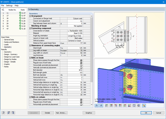
Web cleat connections
- One or two vertical and up to 10 horizontal bolt rows possible at each leg
- Wide range of equal and unequal angles
- Possible to modify angle orientation
- Designs:
- Shear, bearing resistance, and tension design of bolts
- Shear, bending, and tension design of angles considering deduction of bolt hole
- Shear and tension design of girder web considering deduction of bolt hole
- Tension transmission into the column with the T-stub model
- Notching at the critical section
Fin plate connection
- One or two vertical and up to 10 horizontal bolt rows are possible
- Flexible size of the fin plate
- Location of the fin plate can be modified
- Designs:
- Shear and bearing resistance design of bolts
- Shear, bending, and tension design of fin plates considering deduction of bolt hole
- Stability analysis of long, slender fin plates
- Shear and tension design of girder web considering deduction of bolt hole
- Weld as fillet weld
- Notching at the critical section
End plate connection
- Two or four vertical and up to 10 horizontal bolt rows
- Flexible size of the end plate
- Location of the fin plate can be modified
- Designs:
- Shear, bearing resistance, and tension design of bolts
- Shear and bending design of end plates considering deduction of bolt hole
- Shear and tension design of girder web
- Tension transmission into the column with the T-stub model
- Weld as fillet weld
- Notching at the critical section
End plate connection with cleat
- Fixation of the beam by end plate with two bolts
- Flexible size of cleat and end plate
- Designs:
- Load introduction into the beam according to EN 1993-1-5, Chapter 6
- Support of the stabilizing moment by the bolts and welds at the end plate
- Cleat
- Cleat welds as fillet welds
- Tension transmission into the column with the T-stub model
.png?mw=640&hash=c9c52de2eed98a2905a02fbf54b073f645c0df2c)
- Design of moment resistant and simple joints of I-shaped rolled cross-sections according to Eurocode 3:
- Moment-resisting end plate connections (type IH/IM)
- Moment resistant purlin splices (PM type)
- Simple joints with angle cleat and long angles (IW and IG types)
- Simple joints with header end plates mounted either on web only or on web and flange (IS type)
- Check of coped connections (IK) in combination with pinned end plates (IS) and angle connections (IW)
- Automatic design of required joint with bolt sizes (all types)
- Check of required thickness of load-bearing members for shear connections
- Results of all required structural details such as appliances, hole arrangements, necessary extensions, a number of bolts, end plate dimensions, and welds
- Results including stiffnesses Sj,ini of bending-resistant connections
- Documentation of available loading and comparison with resistances
- Results of design ratio for each individual joint
- Automatic determination of governing internal forces for several load cases and connection nodes
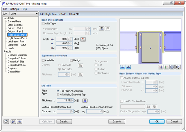
The RF-/FRAME-JOINT Pro add-on module designs connections of structures calculated in RFEM/RSTAB. If there is no RFEM/RSTAB structure available, you can define the geometry and loading manually; for example, when checking external calculations, for example.
Designed nodes are usually imported from RFEM/RSTAB. The module recognizes all connected members automatically and assigns a connection type to them. Depending on the connection type, you can define further details of ribs, backing plates, web plates, bolts, welds, and hole spacing. As loads, you can select any load case, load combination or result combination in RFEM/RSTAB.
In the case of the "preliminary design" calculation mode, RF-/FRAME-JOINT Pro performs the first calculation step to suggest applicable layouts. After you select the relevant layout, the module displays all designs in detailed result tables and various graphics.

- Design of knee joints, T-joints, cross joints, and continuous column connections with I-shaped sections
- Import of geometry and load data from RFEM/RSTAB or manual specification of the connection (for example, for recalculation without an existing RFEM/RSTAB model)
- Flush top connections or connections with bolt row in extension
- Design of positive and negative frame joint moments
- Various inclinations of right and left horizontal beams as well as application to frames of duopitch and monopitch roofs
- Consideration of additional flanges in a horizontal beam, for example for tapered sections
- Symmetrical and asymmetrical T-joints or cross joints
- Two-sided connection with different cross-section depth on the right and left
- Automatic preliminary design of bolt layout and required stiffening
- Optional design mode with possibility to specify all bolt spacing, welds, and sheet thicknesses
- Screwability check with adjustable dimensions of used wrenches
- Connection classification by stiffness and calculation of the spring stiffness of connections considered in the internal forces determination
- Check up to 45 individual designs (components) of the connection
- Automatic determination of governing internal forces for each individual design
- Controllable connection graphics in rendering mode with specifications of material, sheet thickness, welds, bolt spacing, and all dimensions for construction
- Integrated and flexibly extensible settings of National Annexes according to EN 1993-1-8 standard
- Automatic conversion of internal forces from structural analysis into respective sections, also for eccentric member connections
- Automatic determination of initial stiffness Sj,ini of the connection
- Detailed plausibility check of all dimensions, including specifications of input limits (for example, for edge distances and hole spacing)
- Optional application of compression forces to a column through contact
- Possibility to update the cross-section depth of horizontal beams in case of tapered connections after connection geometry optimization in RF-/FRAME-JOINT Pro
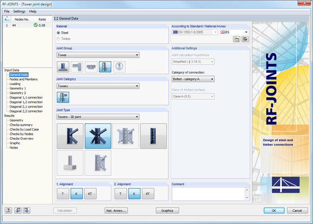
- Wide range of joint types, for example:
- Bolted connection of diagonals without gusset plate 2D
- Bolted connection of diagonals without gusset plate 3D
- Bolted column joint
- T-, K-, and KT-joints considered for connections of diagonals
- Various categories of connections:
- A - shear/hole bearing connection
- B - slip-resistant connection at serviceability limit state
- C - slip-resistant connection at ultimate limit state
- Bolt strength classes of 4.6 - 10.9
- Bolt diameters M12 - M42
- Modifiable bolt spacing
- Visualization of the entire connection in the view window
All joint types are considered with the moment release at the column flange, or at the column web in the case of a rotated column. Therefore, the module determines the eccentric moment of a web cleat and fin plate connection, which additionally affects the bolt group at the girder flange.
Further eccentric moments may result from the locations of the angles and sheets. In the case of cleat connection, the forces are transferred separately. Shear forces act on the cleat; tension forces and stabilizing moment are assigned to the bolts. Before the calculation, the connection is checked for geometrical plausibility; for example, the bolt hole spacing and edge distance of the bolts.